Solar Flare Modelling and Magnetic Reconnection
Background Theory
Magnetic Recconection
The MHD induction equation describes the evolution of magnetic field lines [1]. $$\frac{d\mathbf{B}}{dt}=\nabla \times(\mathbf{v} \times \mathbf{B})+\eta \nabla^{2}\mathbf{B}$$ In the corona we typically have low resistivity so the diffusion term can be dropped and the advection term dominates - i.e in the limit of Magnetic Reynold Numbers $\textbf{R}_{M} \gg 1$. In this regime Alfven's Theorem applies and magnetic flux is 'frozen' to the plasma. In other words, field lines have to move with the plasma fluid particles - if a particle is initially on a field line it is always on thaht field line. This allows us to treat the magnetic field as a physically malleable but unbreakable line.
In this limit it is clear that 'no cutting and pasting' of field lines can occur as the system evolves and hence the connectivity/topology of the field cannot change [2]. Thus for magnetic reconnections to be possible, a finite resistivity must be introduced. This allows for a a non vanishing diffusion term whereby field lines can slip through the plasma and change topologically.
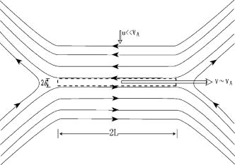
We see that the laplacian of the magnetic field indicates the importance of diffusion and thus topoogical changes are enhanced where there is a rapid change in the field. From $\mathbf{J}=\frac{1}{\mu}\nabla \times \mathbf{B}$ we see that such strong field gradients are associated with large currents. This motivates the most basic 2D model for reconnection where four topologically distinct field regions are separated by a current sheet. This was first introduced by Parker and Sweet in 1957/8.

This steady state model can be shown to have a slow reconnection rate which cannot explain the rapid release of energy observed in solar flares. Petschek made some advancements by introducing a localised diffusion region where the reconnection takes place [3]. Essentially an anomalous electric field acts in this region and is able to reconfigure the field lines. The energy is then dissipated over larger scales outwith [4]. This has the desired effect of increasing the reconnection rate but the physical mechanism behind the non ideal electric field/diffusion region is still not well understood. Much work continues to be explored in this area!
Post Reconnection Flux Tube Dynamics
Assuming the magnetic reconnection mechanism works, we can examine the post reconnection dynamics in order to understand the release of magnetic energy. Here we will discuss the setup proposed by Longcope and Klimchuk based on thin flux tubes (TFT's) [4].
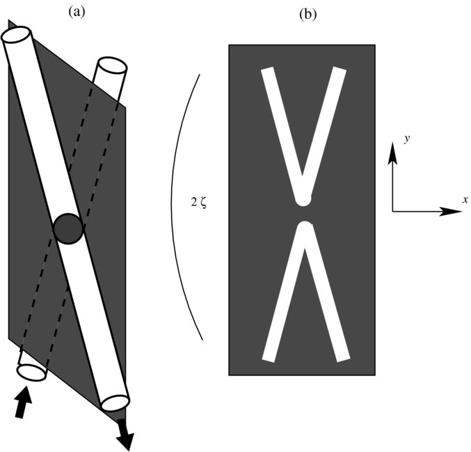
We consider two uniform magnetic domains separated by a current sheet. The field lines run parallel to the current sheet plane but are orientated at a relative angle or shear $\Delta \theta$. This is best illustrated using the figure produced by Longcope and Klimchuk as seen below. The reconnection event then occurs within a localised diffusion region as seen in the accompanying diagram taken from Guidoni and Longcope [5].
With the thin flux tube set up, the evolution follows the governing equations of a one dimensional gas-dynamic model as parameterised along the coaxial length coordinate $l$ [4].
The Energy Equation:
$$c_{v}\rho \left(\frac{dT}{dt}\right)=-p\left(\hat{\mathbf{l}}\cdot\frac{\partial \mathbf{v}}{\partial l}-\frac{d \ln{\mathbf{B}}}{dt}\right)+\mathbf{B}\frac{\partial}{\partial l}\left( \frac{\kappa}{\mathbf{B}}\frac{\partial T}{\partial l}\right)-n_{e}^2\Lambda(T)+\frac{4}{3}\mu\left(\mathbf{\hat{l}}\cdot\frac{\partial \mathbf{v}}{\partial l}\right)^2+H(l,t)$$ The terms on the right hand side all have correponding physical interpretations:- Adiabatic work
- Thermal Conduction
- Radiative losses
- Viscous heating prominent in shock fronts
- Necessary heating to maintain coronal equilibrium temperatures
The Momentum Equation:
$$\rho\frac{d\mathbf{v}}{dt}=\left(\frac{\mathbf{B^2}}{4\pi}-p\right)\frac{\partial \mathbf{\hat{l}}}{\partial l}-\left(1+\frac{4\pi p}{\mathbf{B^2}}\right)\times\nabla_{\perp}\left(\frac{\mathbf{B^2}}{8\pi}\right)-\mathbf{\hat{l}}\frac{\partial p}{\partial l}+\rho \mathbf{g}+\frac{4}{3}\mathbf{B}\frac{\partial}{\partial l}\left[\mathbf{\hat{l}}\frac{\mu}{\mathbf{B}}\left(\mathbf{\hat{l}}\cdot\frac{\partial \mathbf{v}}{\partial l}\right)\right]$$ Again the RHS terms all have a physical meaning:- Tension acts to straighten field curvature
- Effect of surrounding magnetc pressure
- Plasma pressure gradient
- Gravitational body force
- Non conservative viscous effects
With the dynamical equations in place we have the framework to evolve the flux tube through time. Note that we operate exclusively in the ideal induction limit after reconnection has occurred hence the field is frozen to the plasma and the 3D complexities reduce to a 1D problem! Here I will qualitatively describe the various stages of the retraction and how this corresponds to the magnetic energy release.
The retraction is driven by the magnetic tension force due to the curved configuration of the thin flux tube - pulling the top of the tube downwards. This causes the formation of two bends connected by a horizonntal straight segment - these are the 'Rotational Discontinuity' modes which propagate at the Alfven speed down the legs of the retracting field [6]. These can be thought of as the shock equivalents of Alfven waves - indeed this makes intuitive sense as both propagate via the restoring effects of magnetic tension without disrupting pressure or density.
Note, as the tube retracts we assume that the field strength remains unchanged. This is because fast magnetosonic waves dissipate any pressure imbalance on a time scale much less that the dynamical Alfven velocity [5]. Since we are operating in the regime $\beta \ll 1$ the pressure is dominated by the magnetic contribution - essentially $\frac{\mathbf{B^2}}{2\mu}\gg P$. Hence this implies that the magnetic strength is fixed throughout the system.
This shortening of the flux tubes directly infers the release of energy. Since the total magnetic energy is found by integrating the field energy density throughout the flux tube, as the tube shortens, the field energy decreases [4]. $$W_{M}=\frac{1}{2\mu}\int\mathbf{B}^2dV=\int d\phi\left(\frac{1}{2\mu}\int B dl\right)$$ Since flux is frozen into the plasma and the field strength is constant only the inner integral can change by the reduction of tube length. So, how is this energy released?
As the flux tube is accelerated downwards the bend pushes plasma along the horizontal segment towards the centre. This causes a collision at the centre as evidenced by a density spike in the numerical models. This is termed the 'Slow Mode Shock' [4] or 'Gas Dynamic Shock' [5] and it advances outwards as time progresses. Due to the constant nature of the magnetic field strength, this can be regarded as a completely hydrodynamic phenomenon - simply an acoustic shock front!
The enhanced density is coupled with viscous heating in this region - raising the temperature and offering a suitable energy release mechanism which could explain observed solar flare loop-top emissions! According to Longcope, Qiu and Brewer [6] this is responsible for 20% of the energy made available due to the retraction.
The remaining energy is transported thermally in conducting fronts which propagte faster than the Alfven velocity of the rotational discontinuity bends [4]. They eventually reach the cool, dense chromosphere which is pressurised, heated and evaporated. Thus we should expect to observe a rising velocity signature from the footpoints. This is also coupled with an oppositely orientated "chromospheric condensation" as the pressure pushes some material further down.
Eventually the tube retracts to the top of the loop flare arcade where it now remains [6]. The shocks initiated by the retraction continue to contain the loop top density concentration for some time - temporally extending the emission. The evaporation fronts collide in the centre and rebound before motions begin to subside and remaining energy is radiated - the system tending towards an isobaric equilibrium [6].
| Ⓒ Callum Fairbairn 2017 |  |
 |
